Carriage 1
The first carriage is to be a sit astride combined driving and passenger car which as previously mentioned is currently under construction. Watch this space for reports on progress.
September 05; The carriage was originally commenced in @ 1990 by constructing a body from scrap plywood and hard wood offcuts glued together using left overs in the pot of "West" epoxy during boat building. The body is 4' long so will accomodate an adult driver and three young passengers in relative comfort. The main essential thing missing at present is the underframe and wheels. So the first step was to obtain eight steel discs to machine up some wheels for the bogies (a quick assesment decided that four wheels on a carriage of this size was definately a non starter!). It then occured that some effort ought to be made to locate the body in it's dark and dusty resting place. It was recovered with some difficulty dusted off and found to be in relatively good shape although the paint had suffered from the damp. A start has been made on facing the wheel discs to thickness and boring in readiness to mount on a mandrel and machine the treads. The pictures below show the carriage body posed neatly where the track will go and one of the wheel discs during machining.
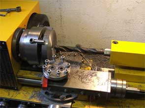
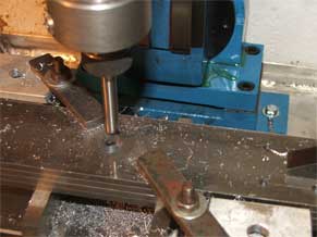
March 06; Finally the wheels have been completed. All the discs were bored to 0.627" and a mandrel turned up to mount them on in the lathe in turn, to machine the treads, at the same time the opportunity was taken to turn up all the tender wheels required for Wotan and Dixie. The carriage axles were turned to fit the wheels and the wheels loctited on. The design for the bogies has evolved as production has progressed, one problem was locating suitable bearings. The ideal in mind was a flange mounted self aligning ball race that could be bolted directly to the bogie side frames. The self aligning function was to enable an "equalising" bogie to be constructed (unsprung) to deal with any track irregularities, springing it was felt would be detrimental to the stability of the carriage. No suitable steel housed bearings were found that would keep the overall dimensions of the bogie within the existing confines of the body, but some self aligning composite plain bearings within a four bolt nylon housing were located at reasonable cost and it was decided to try these to see how they perform. Material was obtained for the side frames and centre bodies from John at Folkestone Engineering Services (an excelent supplier for model engineers I have to add!) and construction continued. The LH picture below shows all four side frames clamped together on the table of the milling machine for the centre pivot holes to be machined using the boring head. The RH picture shows the trial assembly of side frames and wheels of one of the bogies, the centre pivot hole visible that will provide the equalising function in combination with the self aligning bearings. Limit stops will be provided on the centre frames to prevent excessive movement.
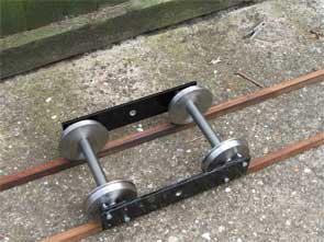
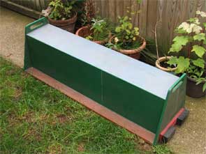
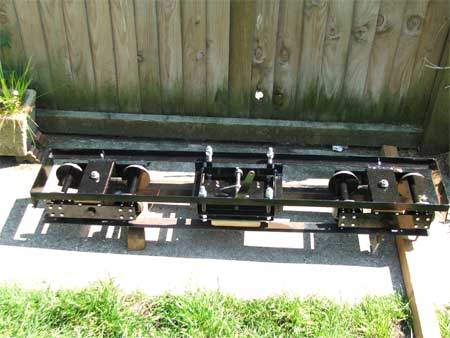
May 06; The bogies have now been completed, the centre bolsters being welded up from 2.5mm flate plates in a carefully chosen sequence to minimise distortion. However despite the care taken on completion they were just under 0.5mm too narrow so that when the side frames were assembled the bearings were tight against the axle journal shoulders making the wheels very stiff to turn (obviously undesirable). Following much head scratching the simplest solution was decided as putting a very slight bend in the side frames to provide @ 0.15mm end float. This was achieved in the vice with a large hammer and a block of hardwood using some trial and error! The chasis was a simple welding job from 25mm x 25mm x 3mm BMS angle and 2.5mm flat plate, then came the brake! It had previously been decided to use a "skid" brake acting on the top of the track but one danger of this type of brake is over enthusiastic application can lift the wheel flanges clear of the rails and derail the car. To counter this a positive stop was adopted by fitting locknuts to the plate supporting the brake block and adjusting with the chassis assembly on the track so that when the brake is applied it can just take the full weight of the car but does not lift the wheel flanges clear of the rails. All materials for the construction of the brake and operating linkages were dug out of the scrap box with the exception of the 10mm studding and nuts which were purchased for the job. The picture below shows the completed chasis stood on my loco unloading ramp on the garden path. The brake plate and operating cam / linkage can be seen in the centre of the chasis and you can also see the alan screws fitted to the bogie bolsters which limit the articulation of the side frames on the centre pivots. All that remains is some final drilling and bolting to marry the chassis up to the body and paint the body. it is hoped the carriage will be finally finished before the end of the month.
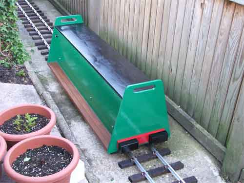
Finally, the moment of truth! The carriage is placed on the track for the first time.There is still some minor assembly to be done in fitting the brake linkages and operating lever and the couplings but all the parts are made so this is only an hour or so's work!