Durining the first run on the Fox Hollow line the knocking that had been present in the connecting rods for some time became more noticiable. The following weekend after repairing the lubricator clack valve saw an outing to the local club track and the clanking rods nearly drove me mad over the course of the afternoon. Having dropped the fire and cleaned down at the end of the day I headed home with a strong resolve to "sort it out"!
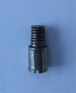
Back in the workshop the left hand connecting rod was removed and the bearing hole measured which showed ovality of 0.030". The crosshead pin was also found to be badly worn although the rod eye was reasonably unscathed. The coupling rod was also checked and found to be worn oval by @ 0.010" on the rear bearing hole. For those unfamiliar with the Maxitrak methods of construction the coupling and connecting rods are gunmetal castings which are machined to run directly on the crankpin without the need for bushes. The front crankpin however is a shouldered countersunk socket head screw. See below for pictures of the large end bearing of the connecting rod and the worn crosshead pin.
Having stripped the motion down and seen the wear the next stage was to carry out a repair but more importantly although the loco has covered a considerable mileage try to make some improvements to slow down any future wear. Considering the second point, improved lubrication may certainly assist and as built it was noted that there is no means of introducing oil directly onto the bearing surfaces. With regards to the large end of the connecting rod and the bearings of the coupling rod it is possible that oil applied externally may enter the bearings but in the case of the cross head pin there is no easy means of applying oil. With regard to the repair it was decided to machine out and fit parrallel "thin" walled bronze bushes to the coupling and connecting rod where they run on the rear crank pin. The coupling rod running on the front crankpin due to the countersink would be more difficult to address and would require manufacture of a new crankpin and locking arrangement, therefore it was decided to leave this as is. It was also decided to produce new cross head pins of silver steel running in the original bores of the small end of the connecting rod as most of the wear was on the old pins. In an effort to improve lubrication the new cross head pins were made hollow with a 0.055" bore and cross drilling to the bearing surface. This will allow application of an oil can to the end of the pin forcing oil directly into the bearing. The remaining three bearings of the coupling and connecting rods were drilled from the top to allow injection of oil in a similar fashion.
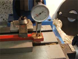
The first stage of the repair required the worn holes in the rods to be bushed, to be machined out oversize to accept the bushes. Each rod was clamped in turn on a parrallel to the table of the mill and clocked concentric with the spindle axis.
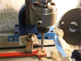
The clock was then exchenged for the boring head and the holes machined out to accept bushes of 0.0625" wall thickness.
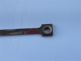
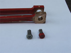
Bushes were then machined in the lathe with a 0.001" interferance fit. A steel press tool was also turned to assist with pressing the bushes home in the jaws of the vice. Once the bushes were pressed home, oilways were drilled through the rod on the centre line of the bearing. New silver steel cross head pins were also turned from silver steel according to the revised design. Pictured below are the rods fitted with the new bushes, oil holes drilled and a cross head pin of the new design (on the left) beside one of the originals (with the red paint on the nut).
Following reasembly I decide to take off the steam chest covers and look at the valve timing - shock horror! In fwd gear things were ok-ish but in reverse the front port of the LH cylinder and the rear port of the RH cylinder were not opening at all. Inspection revealed that there was so much wear in the die blocks that there was almost 2mm of lost motion at the valve. A quick juggle of the valve positions on the valve rods improved matters but it was resolved to make new die blocks as soon as time allowed. A test run at the club track showed the performance to be OK and all the noise from the lose bearings to have vanished, so spurred on by this minor success it was back to the milling machine and a lump of gunmetal to produce the new die blocks. For those who are not familiar with the design these are like the TEE nuts that are used in the table of the milling machine which run in corresponding slots in the weighshaft. Instead of the bolt securing the work piece on the machine table the die blocks are fitted with a pin which carries the valve operating link. The new die blocks were machined up @ 0.002" oversize for the slots on the weighshaft and then were gently polished with 1200 wet and dry paper / a needle file to a good sliding fit in the slot. On reconnecting the valve gear on the loco the valve events were much improved but there was still lost motion at the pin and clevis where the valve operating link attaches to the valve rod just behind the cylinder. Dismantling this revealed another horror. At some point the operating link had ben bushed but the OD was such that it had broken through the outer profile of the rod which had been silver soldered back together, the resulting hole for the bush being oval. The bush had obviously been a poor fit in the rod and had almost disintegrated, hence the slack. Really the only correct solution was to manufacture a new rod but not wishing to spend the time at thisd point an Engineers Work-around (bodge in laymans terms) was devised. There being insufficient material to machine out the hole in the rod to a regular and round profile it was filed round checking with the internal jaws of the vernier to get a hole round to within @ 0.003". A bush with an OD of the nominal hole size plus 0.003" was turned in the lathe and forced into the rod using the vice as a press. Reassembly to the loco showed no play and the valve tioming was then reset to the best approximation of correct events possible taking account of the slight difference in valve travel between forward and reverse.
Gleefully I returned to the FHLR and steamed up. the first couple of trips up and down the line were adequate but not stunning. However with more trips the performance deteriorated to the point where the loco failed to move at all in reverse, in fact when opening the regulator it locked totally when going in reverse. Removing the LH steam chest cover showed the cause of the problem. The valves are located on the rods by a circular collar at each end, these are locked to the rod with a socket head grub screw. The grub screws are mild steel and a silicone product had been applied over them to keep out the steam and supposedly prevent rust. This had not worked and the hex key slipped in the screw when tightening / loosening. It was felt that the screws were tight enough but actually they were not and the rear collar had slid down the valve rod which meant the valve was not moving forwards at all! I believe that when cold the pressure on the screw was adequate as the loco ran fine on air when the timing was set. However the collars are brass and the rods and grub screws steel and I believe when hot the expansion was sufficient to reduce the clamping effect of the screws and allow the collar to slip.
Back to the workshop! The hexagons were so badly worn that the screws could not be removed but an "easyout" (lefthand threaded spiral designed for removing broken studs and bolts) was found in the toolchest that locked into the heads of the screws an allowed them to be removed. The left hand ones were found to be 2BA and the right hand 6BA. I could not find a ready supplier for stainless steel screws of this thread so working on the theory that the mild steel versions had lasted a good few years they were replaced with new mild steel screws and sealed over the top with silicon as before once the timing was reset. Another trip to the club track showed performance to be much improved so now another trial on the FHLR is to be arranged.