DEVELOPMENT
Hagan was born out of the wish to get a running loco which was cheap, quickly built and safe for the children to drive on the local club track. This really precluded steam power on all three counts. Having already had a 3 1/2" gauge Juliet with inside Stephenson link valve gear under construction for some years (since school in fact!) this project was put aside in favour of the new loco. Some of the commercially available kits such as Maxitrak were initially considered as a way of fitting the bill but were discounted due to the first constraint - cost. In fact on completion of the loco the total cost of all materials purchased including paint was less than £350. Once it was decided that the loco would have to be home built thoughts turned to the planning stage, a few "fag packet" sketches were produced and some odds and ends such as the tooth belt drive pulleys collected. An advert was seen for a limited number of Sinclair C5 motors and one was duly ordered together with a kit for a speed controller. The physical size of the loco was determined by the wish to mount the motor transversely accross the frames, this required a narrow gauge outline and outside frames. Not wishing to purchase more expensive cast spoked wheels the outside frames were also an advantage in trying to maintain a realistic look with more simple disc wheels. Having a broad plan in mind some of the more important details were considered such as the required gear ratio of motor to axle for the chosen diameter of wheels to give a reasonable speed whilst maintaining torque, as our local club track has quite a long gradient and the loco was expected to haul all of our four children around this track. It was decided to achieve the required gear ratio a layshaft would be employed connected to both axles by chains. This meant the diameter of the pulleys and sprockets could be kept to reasonable proportions and all four wheels would be driven reducing the liklihood of slip. Having determined the reduction given by the toothed belt pulleys and measured the free running rpm of the motor the size of the chain sprockets were determined and these were ordered along with steel blanks for the wheels.
Considering the initial objectives of cost, speed of construction and young driver capability I was very happy with the end result. The cost compared with commercial products was very reasonable, although construction spanned a period of two and a half years the actual hours spent in the workshop were not that excessive (due to my job as a marine engine service engineer traveling to ships worldwide, time in the workshop was limited to short concentrated bursts). The end result has a pleasing appearance (to me anyway) and it's performance has to date been very reliable with only one problem when the large toothed belt pulley worked loose on the layshaft. Due to the size of the wheel boss a mechanical lock such as a pin was not practical so it was machined as a press fit, unfortunately again due to the size of the boss and the material it lacked stability and the boss expanded when it was pressed on. When it worked loose the fit was eased and loctite high strength retainer was employed, no further problems have been experienced.
CONSTRUCTION
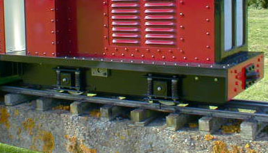
Being a professional engineer and having a small but reasonably well equiped workshop with a Hobbymat MD65 lathe, off hand grinder, pillar drill, selection of hand tools, taps, dies and drills, battle commenced with hacksawing and filing out the frames and buffer beams. This took a while as being involved with heavy engineering and not wanting the thing to suffer wheel slip these were hacked out of 1/4" steel plate, obtained for the very reasonable price of £5 from a small local metal merchant. At this point whilst the major dimensions of most of the componants had been decided the method of suspension had not. I had in the workshop eight springs of around the right proportions (being a believer in "if it looks right it probably is"). The springs were arranged in four groups of two, a piece of plywood placed on top and then the motor, frames, a car battery and a few chunks of metal were added to simulate the weight of the body and incidentals. the whole "pile" was then rocked around on the springs noting the deflections and it was decided (in the abscence of anything better) that these springs were ideal. The narrow gauge style couplings were cut out and fitted to the buffer beams and angles cut an bolted to the frames and buffer beams with 5mm hex head bolts to connect the assembly together whilst considering the suspension. The design decided on for the suspension and axle boxes actually turned out to be quite complicated. Double row self aligning ball races were obtained and the axle boxes bored out to accept them with a recess at the back to hold a home made dirt seal. The seal consists of two 1mm thick discs of steel with a neoprene disc sandwiched between, the lip of exposed neoprene in the centre bears on the axle. The seal assembly is retained in the axle box with four 6 BA contersunk screws. A "lawn mower" type grease nipple is fitted in the centre of each axle box and any excess grease escapes by lifting the neoprene clear of the axle, so relieving any pressure. The axleboxes and suspension detail, together with the bearing housing for the layshaft can be seen in the photo below.
The lay shaft is mounted transversly across the frames just ahead of the motor and carried in two sealed ball races, these are mounted in rectangular steel blocks with a hole in each corner. The bearings are a press fit on the shaft so two diagonally opposite holes are tapped and two are clearance, the tapped holes are for jacking bolts to remove the bearings for maintenance if required and the clearance holes are for bolts to secure the housing to the frames. the layshaft was positioned according to the tension of the chains which are quite tight when the loco is supported on blocks and the suspension is at it's lowest point.
The toothed belt drive between the motor and lay shaft was obtained very cheaply from a scrap Qualcast Concord electric cylinder mower. The smaller pulley was not large enough to be bored out to fit the size of the motor shaft so with some trepidation the small protruding stub of shaft at the "free" end of the motor was gripped in the three jaw chuck of the lathe, the tailstock centre inserted into the drive end of the shaft, the body of the motor restrained by a block of wood and a large "jubilee clip" and the shaft was turned down to a suitable size! The pulley was then machined out and loctited to the shaft, a cross hole was then drilled and a roll pin as per the original design of the mower was inserted for good measure.
The motor is mounted on a swing mount, fabricated and welded from 3mm steel although the plastic fins of the motor housing needed some careful trimming before the whole assembly could be fitted to the loco. The initial trials following assembly of the "mosfet" speed controller was spectacularly unsuccesful - nothing happend! Following some ameteur fault finding I had to admit defeat and enlist the assistance of an electronics service to make it work. The bare chasis was tested on the club track using a defunct car battery and gave pleasing results albeit attracting some scathing comments re it's appearance. It was then returned to the workshop for the body to be constructed.
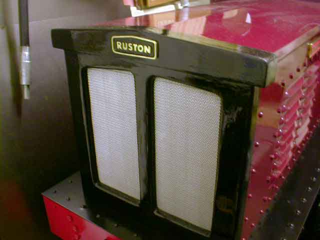
Cardboard patterns were made to mock up the body until a satisfactory appearance was obtained and then 1.5mm sheet steel was cut. Having an affinity for rivets this is how it was joined together. Wishing to provide plenty of ventilation to the battery and motor but being unwilling to spend the time making louvres a chance visit to B&Q for some decorating supplies led to the purchase of two aluminium house vents which were trimmed and rivetted into the body. The cab roof (not having a set of bending rolls) was made from sheet formica glued onto hard wood beams which when sprayed gave a pleasingly fair result. Nameplates were made by silver soldering a surround onto flat brass sheet and then filing individual letters from brass and soft soldering them into position. The radiator was laminated from three sheets of 6mm marine ply glued together and trimmed to the required profile and car body filler mesh was then fitted to form the grille. A diesel sound module, electronic horn and battery state indicator were then fitted and the final job was spray painting (in the garden during a sunny weekend!). Below is a view of the radiator and makers plate (guess which engine manufacturer I worked for!).
PERFORMANCE
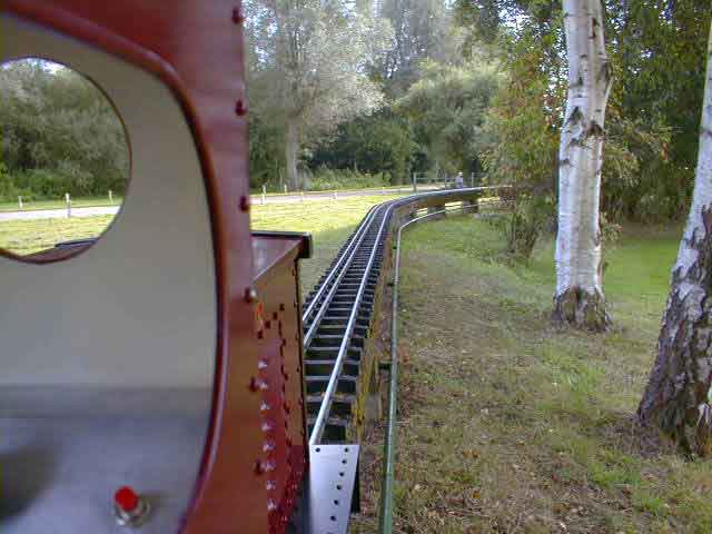
The performance of the loco has been very good. In fact I have spent very little time driving it as the kids are always pulling me off! It happily pulls a single car around our local club raised track and once it was fitted with the body and painted even a die hard steam member has admitted it has a certain character (not sure if this is a compliment though!). The name Hagan is an amalgamation of our twin daughters names Hannah and Megan, my full sized sailing boat being named after our oldest daughter, only our youngest awaits comemoration in steel or wood! Below is a scale drivers eye view from the cab on the club track.