Fairly early on in the project (as stated in the track page) it was decided to construct a point to achieve the required offset from the main line to bring the track up to the back door of the house. Because of the situation of various domestic obstacles such as the rubbish bins and a storage locker it was not possible to continue in a straight line. Constructing a point would enable the maximum length of track from the gate at St James Crossing right up to the backdoor of the house but more importantly it would provide a siding that would allow operation of two trains. With a straight up and down line anything that would add operating interest had to be seriously considered.
Looking around the various suppliers there were plenty of available kits for points or even complete ready made units, the one thing that put me off was the price! So further trawling around the net and an appeal for help on the 5" gauge forum was carried out to try to find some constructional articles or drawings. I did find a few but none giving really good details of the best method of constructing the point blades or the frog (thanks to all those who responded). The next step was to talk to some of our local club members who have ground level lines as to how they did it, as you can imagine advice was plentiful but if anything left me more confused! So the decision was taken to start out on my own making up as I went alomg but bearing in mind probably the most helpful comment I recieved (thanks Steve Kesterton of the Tat Bank railway) "make sure its rigid or you will have problems with derailments". Bearing in mind it has to portable I decided the most vulnerable parts were the blades and frog, so I decided the frog would be a solid lump rather than try to join rails together as I have seen others do. The blades as I had little guidance I decided to make up as I went along. Battle commenced and I have to say with the benefit of hindsight that it turned out a lot more complicated that I imagined and without the milling machine I think the attempt would have been doomed to failure! So here follows the Fox hollow Light Railway guide to point construction. I make no claims for originality of design as I took general ideas from many sources and just incorporated those I liked.
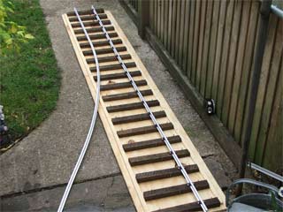
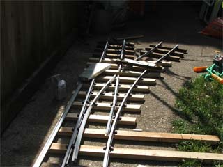
The first problem was deciding the overall radius of the curve. I wanted to keep this as large as possible and certainly not below the 10' commonly accepted minimum for 5" gauge although I understand some have successfully dropped to 8' where space was tight. I began by cutting a number of track profiles from large cardboard boxes in 10' 15' and 20' radii. These were then laid on the path at the proposed site of the point to see how it fitted. It turned out that the first guess of 10' fitted the bill with the best fit, keeping the track on the existing concrete path. Having decided on the radius the long curved rail was bent to the profile of the template (I am using 5/8" or 16mm aluminium rail so this was done over my knee). With the straight and curved rails ready the next step was to decide on the number and size of overlength sleepers. All the standard sleepers on the line are 12" lengths of "tanalised" roofing batten soaked in a creosote tank. I managed to find some more batten in a local builders merchants that was only 1mm thinner than the remaining sleepers (I was pleased with this as the original sleepers were aquired back when timber was sold in feet and inches). The photos below show the start of the project, the dark brown sleepers being standard and the light un-creosoted ones are the new timber. As a first step the jig for positioning the sleepers on the straight track sections was used to try to keep the spacing even.
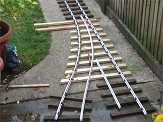
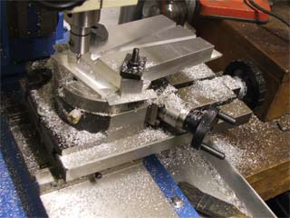
The two grossly overlength sleepers seen at the start of the curve are to support the point change lever. One thing that immediately became apparent was that using the PNP plastic chairs it would be very difficult, if not impossible to bring the point blades together without seriously weakening the rail! This was ignored for now whilst the required position and size of the frog was worked out. It had already been decided to machine the frog from a solid chunk of marine grade aluminium that was to hand (I had seen cast frogs available from suppliers and this was the principle behind the decision). The rails were cut roughly to length and secured temporarily using one screw per chair, the overall dimentions and angles for the frog were determined by drawing / cutting / offering up a cardboard pattern. The raw chunk of aluminium was then sawn roughly to size and transferred to the trusty milling machine. The first machining operations were to square up the sides and face off the ends to the required angle, the overall shape being a trapezium. Machining the steps on the end for the rails to land on were carried out with a fly cutter taking 0.020" cuts at a time, each cut took @ 4 mins to complete and about 5/8" of material in all had to be removed - both ends! I'll leave the maths to you but it took ages! The next step was to mill in the grooves for the flangeways. Only having a 4" rotary table and very small mill it was not possible to mill the curved way to a 10' radius but it was figured that as a curve is really only made up of an infinite number of tangential straight lines making it straight was not the end of the world. It was also decided that slots 3/16" wide would allow for the lack of curvature and also cater for any strange wheel standards of visiting stock (I hear the purists cringing as I write!). Below can be seen the raw chunk of metal (note the track 'gauge' laying beside it) and on the right the last maching operation - cutting the straight "curved" slot!
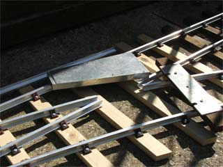
Having completed the frog and temporarily fitted it into position I could now move on to the blades (and lose some more hair!). The shorter curved rail had been bent and cut (as can be seen from the top RH picture) to the full length required including the curved blade so once the frog had been secured in position I already had a curved length of rail to the required radius ready for the blade. The next decision was whether to have the full length of the blade pivoted from the frog or create a "hinge" somewhere in its length and fix part of it. Having looked at many other points and played around with the pieces of rail and an old bogie it was decided to create the hinge about midway along the length of the blade in a suitable gap between sleepers. The hinge was easy just following other full size and miniature practice and bolting a single fish plate to the inside of the rail only. The fixed part of each blade (the straight and curved blades were made together) were then landed on the frog and secured to the sleepers with plastic chairs as the other rails. See below for the main rails, frog and first sections of the point blades secured in position.
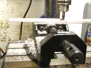
The next step was the most time consuming and puzzling part of the job! It was obvious before any tapering off of the moving parts of the blades was attemted that the plastic chairs would not allow the blades to move close enough to the main rails. I also needed to come up with a means of supporting the moving blades so as the weight of the train passed over them they could not drop but still allow them to slide sideways. The first step was to remove the offending chairs from the main rails, which lead to another problem - how to secure these rails to the sleepers! The solution was found in the scrap box in the workshop. Four pieces of aluminium plate were found that were identical in thickness to the base of the chairs and would just slide beneath the base of the rail and the sleeper. Various pieces were marked out and cut that would sit beneath the rails, long enough to extend under the moving blades which could slide over them. "Clips" were then cut (small rectangular pieces of plate drilled for a securing screw) placed over the aluminium supporting the rail restin over the flat bottom and the screw holes spotted through. screws were then fitted which effectively clamped the rail in position. Next the blades were marked and cut to length so they would end exactly mid way between the sleepers. The curved blade was offered up first and marked out, the outside edge being milled right off (flat bottom and head of the rail) at the correct angle also removing half of the central web. The rail was then turned over in the machine vice and just the head of the rail milled off so at the end it was flush with the centre web. Next the blade was offered up to the point and the inside edge of the outer rail notched away with a file to allow the two rails to come together without a step. This part was very much trial and error as I didnt want the end of the blade to be too flimsy and be damaged by the train wheels but conversely I didnt want to be left with a large step in the outer rail when the blade was open that would cause a derailment! The finished result was actually quite acceptable and so far no problems have been experienced with wear or derailments. The straight blade was treated in the same way although because of the length of the taper required it had to be milled in two steps as there was insufficicient travel on the table of the mill to do it in one hit! Below is the last milling operation on the straight blade.
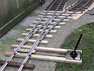
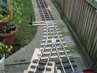
Now I had the main componants all that remained was to secure it all together, make the operating linkage and test it! Another length of aluminium plate was cut that spanned the main rails and this had a small piece of alumnium angle secured on its underside at the mid point. Two small stainless steel brackets were then cut and secured at the ends of the blades by two countersunk M4 screws and nuts. The return of the brackets had clearance holes drilled through which pivot bolts with self locking nuts pass securing them to the span plate. When assembled the span plate slides beneath the the outer rails and the blades rest on the aluminium sliders on top of the sleepers which effectively traps every thing neatly in position and requires only moderate finger pressure to slide the blades accross. An operating levet and base were then fabricated from steel strip, plate and angle riveted together and a bolt used for a pivot. traditionally the operating lever acts parralel to the track operating the blades through a bell crank but it was decided that for the FHLR the lever would also act as a ground level signal indicating which road was set on the point. the lever is connected to the span plate by passing through the angle secured beneath. A washer is welded to the rod one side and the end threaded for a nut, compression springs are fitted each side so that a train passing through the point from either branch onto the main line against the set direction can open the point against the spring without having to manually open the point if required. Initial trials were carried out with a bogie chassis being pushed through the point which was fine in the straight direction but on the curve the wheels tended to run up the slot of the frog and lift off the track - derailing the bogie. I was hoping that check rails would not be required as with the plastic chairs I could not see an easy way of fitting them but this trial showed they would be required! Two short lengths of rail were clamped in the mill vice and the flat botttom milled off each side. They were then laid in position and the locations of the chairs marked and the base of the check rails notched out with a file to sit over the chairs. Three holes were then drilled through the webs of the main and check rails using the fishplate bolt hole drilling jig to maintain the holes square. Spacers were then manufactured and the check rails clamped to the main rails with M4 screws and nuts. Below are two views of the point set in the track ready for testing, see track pages for details.